Tower Safety • RRAT • Forces Are Not Hidden
2:1 Mechanical Advantage Simulator
Adjust load weight, included sling angle, anchor spacing, and friction to visualize true 2:1 mechanical advantage, rope leg tension, horizontal/vertical vector components, and live force-warning status.
Inputs
Wider included angles increase rope-leg tension quickly. Watch the force lights as θ changes.
System Status: Green / within entered limits
Force Status Lights
Sling / Drop Loop Force
SAFEHorizontal Force Fx
SAFEAdjusted Rope Tension
SAFEAnimated Lift Visualization
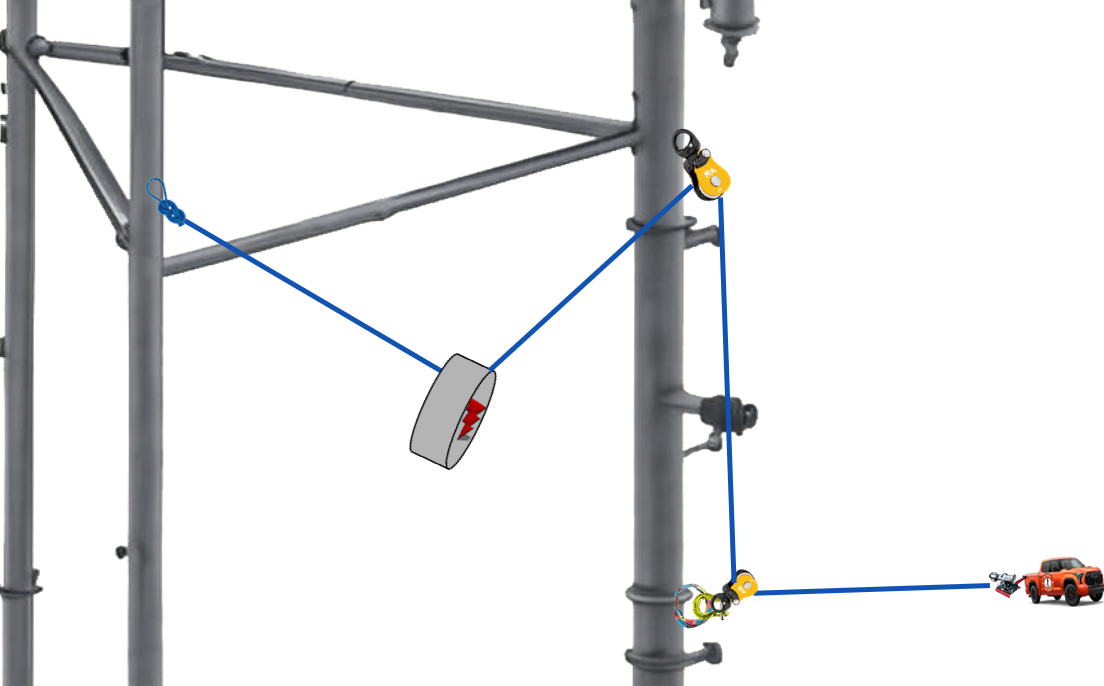
Load Line Length
0 ft
Rope Leg Tension
0 ft
Adjusted Rope Tension
0 lb
Fx Horizontal / Leg
0 lb
Fy Vertical / Leg
0 lb
Actual MA
0.00×
Full Vector Math — 2:1 Mechanical Advantage
Teaching Notes
1. This simulator uses the Excel sheet tab named Drop Loop, updated as a true 2:1 mechanical advantage teaching model.
2. As the included angle between the supporting rope legs opens, the required rope-leg tension increases. This corrects the sling-angle relationship for a 2:1 lift: T = W ÷ [2 × cos(θ/2)].
3. Verify anchors, tower structure, equipment ratings, friction, dynamic loading, manufacturer instructions, and the job-specific rigging plan.