Tower Safety Static Tag Line with Trolley Simulator

Lift #4   |   Learn • Lead • Live   |   Forces Are Not Hidden

Rigging Lab

Inputs

Enter the trolley distance in feet. Position percentage and both static-line span lengths are calculated automatically.
Optional Inputs
Prescribed loaded geometry for teaching. This is not a rope-elasticity, pretension, or full catenary calculation.
Equipment & Attachment Ratings
Enter manufacturer-rated capacities and the sling WLL for the actual hitch configuration. Utilization is calculated from these entered values and does not replace Qualified Person review.
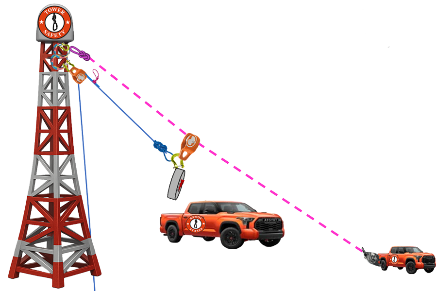
Static tag line with trolley rigging system

Results

Load-Line System
Top Pulley Reaction
Top Pulley Fx / Fy
Load-Side Line Tension
Hoist-Side Line Tension
Force Transferred into Trolley
Transferred Fx / Fy
Static-Line System
Tower Static-Line Reaction
Static Tag-Line Tension
Left / Right Span Tension (Equal-Tension Model)
Static Anchor Reaction
Anchor Fx / Fy
Equilibrium Check
Angles & Geometry
Vertical Load-Position Angle
Top-to-Load Line Angle
Top-to-Hoist Line Angle
Top Pulley Included Angle
Static-Line Chord Angle
Left / Right Loaded-Span Angle
Static Line Span
Trolley Distance
Trolley Position
Prescribed Loaded Sag
Equipment Utilization
Load Line
Top Pulley
Trolley / Dedicated Pulley
Static Tag Line
Tower Static-Line Attachment
Static-Line Anchor
Trolley Connection Sling
Entered WLL Status
Amplification Summary
Top Pulley
Trolley Transfer
Static Line
Static Anchor
Critical Angles

Live Warning — NORMAL

Adjust the inputs to evaluate the lift.

Math & Teaching Notes

v2.0 free-running trolley model: The trolley is modeled as freely moving on one continuous static tag line. Therefore, the left and right static-line span tensions are equal. The simulator solves the static tag-line tension and load-side line tension simultaneously from two-dimensional equilibrium; load-side tension is not assumed to equal gross load.

Equilibrium: Gravity, the solved load-line pull, and the equal-tension static-line span vectors satisfy ΣFx = 0 and ΣFy = 0 at the trolley/load assembly. The displayed residual should round to approximately zero.

Model boundary: This model applies to an ideal free-running trolley. A restrained, braked, clamped, or friction-controlled trolley requires an additional measured or engineered constraint and shall not be represented by this equal-tension model.

Loaded sag: The sag input prescribes the loaded trolley geometry. It does not calculate sag from rope diameter, construction, pretension, elasticity, self-weight, temperature, or a full catenary model.

Anchor reaction: One static tag-line segment terminates at the anchor, so the anchor reaction equals the solved continuous static-line tension. It is displayed separately to distinguish internal rope tension from force applied to the anchor.

ANSI/TIA-10.48 Warning: Straight tag lifts for lift systems attached to the structure with vertical load-position angles exceeding 10 degrees, and/or horizontal tag angles exceeding 70 degrees regardless of gross load shall be treated as requiring additional review. This simulator evaluates the vertical load-position angle from the displayed geometry.

11.5.4 Wind Limitations: The nominal wind speed considered for standard load-chart values is 30 mph at the elevation of the gin pole. Wind above 30 mph shall be treated as a special engineered lift in accordance with the applicable evaluation and special-lift parameters.

Important: Blue/yellow/orange/red values indicate force amplification relative to dynamic lifted load. They are not equipment-capacity or WLL ratings and do not approve a lift. Verify every rope, pulley, connector, tower attachment, hoist, and anchor with a qualified person and the site-specific rigging plan.