Tower Safety Rigging Lab
Trolley / Self Tagging Lift Simulator
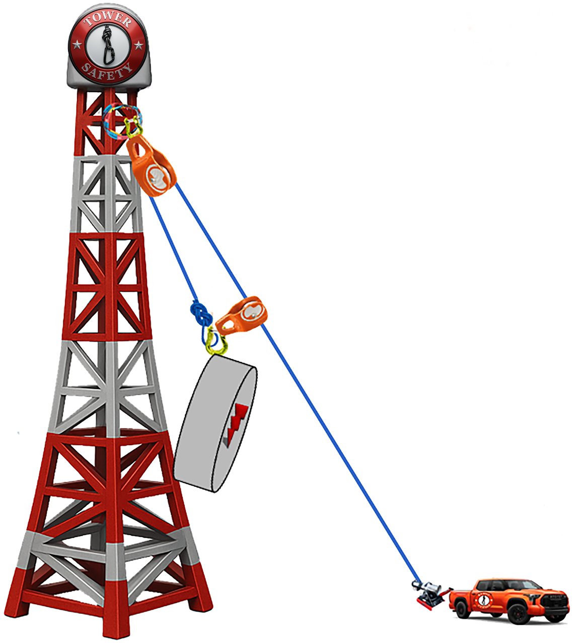
Top pulley • travelling trolley pulley • Forces Are Not Hidden
SAFE All forces are within training limits.
TOP PULLEY — lbf
TRAVELLING TROLLEY — lbf
LOAD — lb
⚠ Forces Are Not Hidden
Moving the trolley changes the load path, line angle, travelling pulley force, and resultant anchor force.
Moving the trolley changes the load path, line angle, travelling pulley force, and resultant anchor force.
Inputs
Trolley Self TaggingResults
Blue • Yellow • Orange • RedAll forces are within the training threshold.
Top Pulley Force—
Travelling Pulley Force—
Resultant Anchor—
Fx / Fy— / —
Load Line Angle—°
Wind Status—
Fz Teaching Value—
ANSI/TIA-10.48 Warning
Straight Tag Lift: Straight tag lifts for lift systems attached to the structure with vertical load position angles exceeding 10 degrees, and/or horizontal tag angles exceeding 70 degrees regardless of the gross load shall be treated as requiring additional review.11.5.4 Wind Limitations: The nominal wind speed considered for standard load chart values is 30 mph at the elevation of the gin pole. This does not mean lifts can be, or shall be, conducted with wind speeds up to 30 mph. Other factors including specific site conditions, load control parameters, and the types of objects being lifted shall be considered when making this evaluation.
Above 30 mph: Lifts in nominal wind speeds above 30 mph shall be considered special engineered lifts in accordance with ANSI/TIA-322-A with applicable evaluation and special lift parameter conditions applied.